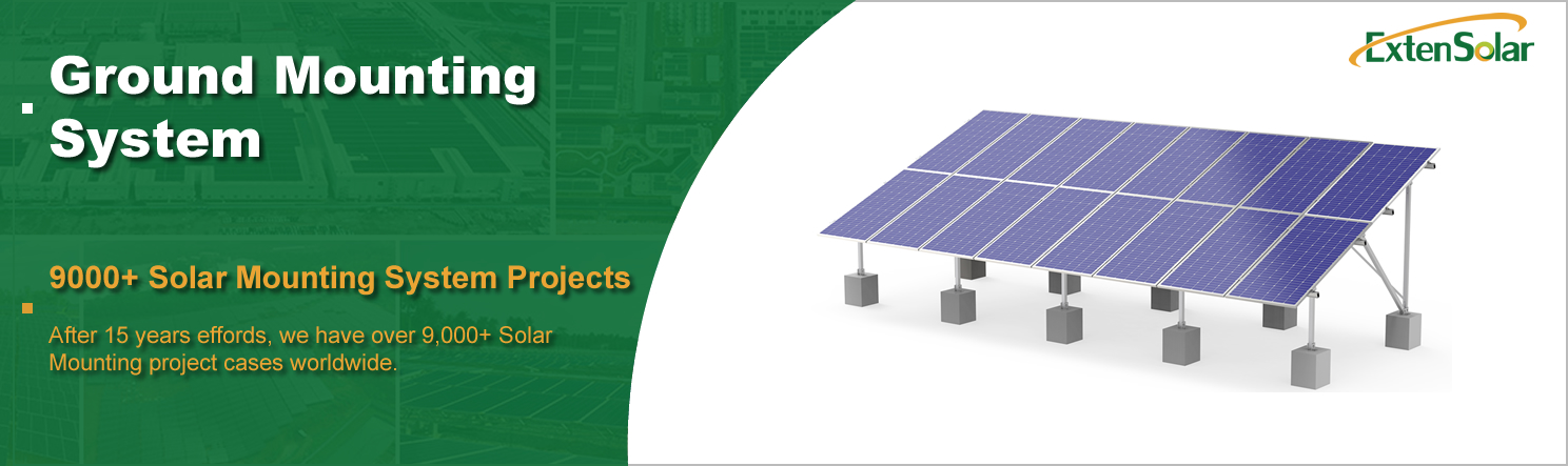
Details
| Surface Treatment |
Anodized |
Material |
Aluminum Alloy 6005-T5 |
| Place of Origin |
China |
Installation Site |
Open Field |
| Brand Name |
Exten |
Model Number |
A02-1 |
| Standard |
|
Certificate |
AS/NZS1170.2/CE/ISO |
| Wind Load |
60m/s(196.85ft/s) |
Module Orientation |
Landscape Portrait |
| Wind speed |
Yo 60m/s |
Max Snow Load |
1.4KN/m2 |
| Snow Load |
1.4KN/m2(29.24psf) |
Service Life |
25YRS |
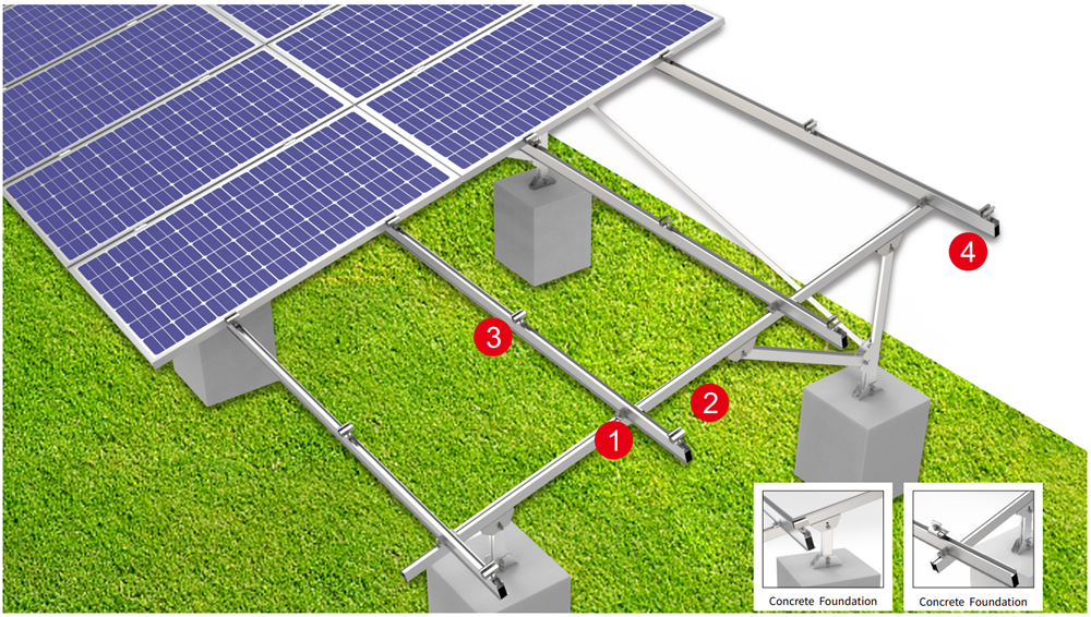
Component List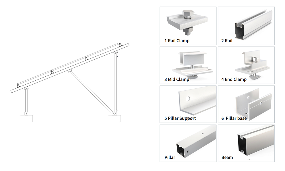
| Description |
Material |
Specificatioin |
Quantity |
| Rail |
AL 6005-T5 |
6080mm |
4 |
| Rail |
AL 6005-T5 |
3040mm |
8 |
| Beam |
AL 6005-T5 |
2800mm |
4 |
| Pillar |
AL 6005-T5 |
229mm |
4 |
| Pillar |
AL 6005-T5 |
764mm |
4 |
| Beam suppirt |
AL 6005-T5 |
929mm |
4 |
| Pillar suppirt |
AL 6005-T5 |
2700mm |
2 |
| Rail splice |
AL 6005-T5 |
250mm |
8 |
| Rail clamp |
AL 6005-T5 |
45mm |
32 |
| Hinge connector |
AL 6005-T5 & SUS 304 |
155mm |
24 |
| End clamp |
AL 6005-T5 & SUS 304 |
60mm |
8 |
| Mid clamp |
AL 6005-T5 & SUS 304 |
60mm |
28 |
| Al nut |
AL 6005-T5 |
20mm |
36 |
| Pillar screw 01 |
SUS 304 |
|
16 |
| Pillar screw 02 |
SUS 304 |
|
16 |
Vertical Ground Mounted PV Panels Advantages
Vertical mounting systems position the modules perpendicular to the ground, significantly reducing the east-west footprint. This allows for more arrays to be installed on the same land area, making them particularly suitable for projects with high land costs or limited available space.
Next, consider self-cleaning capabilities. When modules are mounted vertically, rainwater and snowmelt naturally run down the glass surface, washing away accumulated dust and bird droppings. This reduces the frequency of manual cleaning by approximately 60% compared to horizontal or tilted mounting systems. In winter, snow cannot accumulate on vertical surfaces, virtually eliminating the risk of excessive snow loads and saving on snow removal labor costs for projects in northern regions.
Third, the wind resistance mechanism differs. The wind pressure coefficient of a vertical structure is entirely different from that of traditional tilted mounting systems—when wind blows from the front, the airflow splits vertically along the module surface, resulting in an actual lift force that is actually lower than that of tilted panels. Wind tunnel tests show that, with the same counterweight, the vertical configuration’s resistance to overturning is approximately 20% higher than that of a horizontal tilted configuration.
Fourth, electrical yield is optimized. Vertically mounted bifacial modules can simultaneously harness direct sunlight on the front and ground-reflected light on the back. Especially when the surface features highly reflective gravel or light-colored vegetation, the rear-side gain can reach 10%–15%. Under low-angle sunlight in the morning and evening, vertically mounted modules receive sunrise light earlier than fixed-tilt mounts, extending the effective power generation period.
Fifth, maintenance aisles are naturally formed. The large vertical spacing between modules allows maintenance personnel to walk upright between the arrays without having to crouch or crawl, significantly improving operational efficiency when replacing inverters or inspecting junction boxes.
Finally, the system offers high weather tolerance during construction. With the center of gravity of the vertical-panel frame directed straight downward, the sway during installation in high winds is less than that of horizontal large-panel structures, ensuring safer hoisting operations. Construction can resume as soon as wind and rain subside, avoiding frequent work stoppages due to gusts.
Ground Solar Mount Installation
Step 1: Lay out and mark positions. Use a total station to mark the centerlines of each row of brackets and the base positions, keeping the error within ±20 millimeters.
Step 2: Hoist and position the counterweight bases. Place the precast concrete strip foundations or sand-filled steel boxes at the marked points according to their numbers, and perform a preliminary leveling adjustment.
Step 3: Install the vertical columns. Connect the bottom flanges of the columns to the embedded bolts in the bases, and use temporary diagonal braces to secure vertical alignment.
Step 4: Perform precise plumb adjustment. Use a dual-axis level to adjust the longitudinal and transverse verticality of the columns, ensuring deviations do not exceed 1°, then tighten the nuts.
Step 5: Install the cross-braces and module mounting brackets. Connect the transverse stabilizing beams between the columns, then install the upper and lower mounting clips for the photovoltaic modules.
Step 6: Hoist the modules into place. Use specialized lifting equipment to vertically insert the modules into the mounting bracket slots, sliding them into position from top to bottom, and secure them with locking blocks.
Step 7: Electrical Connections and Grounding. Run positive and negative cables along the cable trays on the posts and connect them to the string inverter. Measure the insulation resistance and ground resistance. Finally, use a torque wrench to spot-check 10% of the bolts for torque, and conduct a full-system lateral push test—apply a horizontal thrust equivalent to 110% of the design wind speed at both ends of the array; if no displacement is detected, the system passes acceptance.
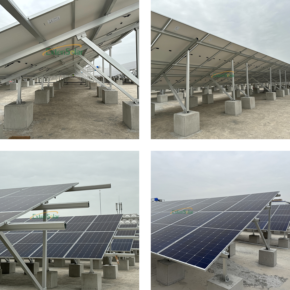
Ground Solar Panels Case
FAQ
Q: Is the tilt angle of the vertical mounting system fixed or adjustable?
A: The factory-set tilt angle is 80° or 90°, and cannot be significantly adjusted on-site. However, the columns on the base feature three height adjustment holes, allowing for fine-tuning of ±5° to accommodate different latitudes or ground reflection conditions.
Q: Are the counterweights larger and heavier than those for the horizontal configuration?
A: Yes. Because the lever arm is shorter, each meter of the array requires approximately 600–900 kilograms of counterweight, which is 30%–50% more than the horizontal configuration. However, the longitudinal spacing can be increased, so the total steel consumption per mu is not significantly different in practice.
Q: How is rear shading handled?
A: The rear-row modules do not shade the rear of the front row because the vertical array is arranged in a staggered pattern, and the spacing is calculated to ensure no shading between 9:00 a.m. and 3:00 p.m. true solar time on the winter solstice, thereby fully preserving bifacial yield.
Q: Are the cables exposed?
A: All DC cables are routed through enclosed cable trays along the inner sides of the vertical posts; the trays are equipped with waterproof rubber seals. Connectors are housed in maintenance boxes 1.2 meters above the ground, facilitating easy connection and disconnection while preventing damage from animals.
Q: Is this system suitable for areas prone to sandstorms?
A: Yes. The vertical panels provide strong wind sweeping action, preventing sand particles from accumulating in the central area of the glass. It is recommended to install sand-proof panels at the base to prevent sand accumulation from burying the base, thereby extending the maintenance interval to once per quarter.


